Character Animation System
Lyra animation Blueprint architecture, thread-safe updates, layered animation interfaces, Distance Matching, and Control Rig Foot IK
This chapter explains the animation system built on the Lyra architecture, including thread-safe updates, layered animation interfaces, Distance Matching for reducing foot sliding, and procedural physical correction through Control Rig Foot IK.
4.1 Technical Selection: Why Use the Lyra Architecture?
Section titled “4.1 Technical Selection: Why Use the Lyra Architecture?”| Approach | Strengths | Why It Does Not Fit This Project |
|---|---|---|
| ALS | Extremely high realism | Complex Blueprint math occupies the game thread CPU. Its monolithic architecture is highly coupled, becomes exponentially harder to extend, and does not fit GAS well. |
| Motion Matching | Very natural motion transitions | Requires high-quality motion-capture data and is not suitable for a solo project. It is fundamentally a fuzzy search system, so transitions are less predictable. |
| Lyra (✅) | High-performance multithreading and modular low coupling | — |
This project is strongly action-oriented and emphasizes responsiveness and precise attack validation. Lyra’s state-machine-based approach provides stronger deterministic control, ensuring that combo and dodge feel remains precise and reproducible.
4.2 Core Technical Advantages of the Lyra Animation Architecture
Section titled “4.2 Core Technical Advantages of the Lyra Animation Architecture”| Feature | Traditional Approach | Lyra Architecture |
|---|---|---|
| Data update | Event Graph processing on the game thread, affecting CPU performance | Thread Safe Update Animation, moved to worker threads for parallel execution |
| Data access | Blueprint nodes read values one by one, with higher overhead | UE5 Property Access reads efficiently from the C++ layer and caches native Float / Bool values |
| Architecture coupling | Monolithic AnimBP with tightly coupled logic | Anim Layer Interface decouples layers and separates logic from presentation |
| Extensibility | Changing one place can affect the whole graph | Dynamically linked Layer assets allow new weapons or characters without modifying the base logic |
4.3 Player Character Example: Lyra Architecture and Procedural Animation Correction
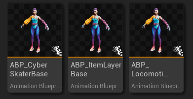
Section titled “4.3 Player Character Example: Lyra Architecture and Procedural Animation Correction”Using the player character animation Blueprint ABP_CyberSkaterBase as an example, I divide the animation flow into three parts: the data-driven layer, the graph-layer architecture, and the presentation execution layer.
4.3.1 Thread-Safe Data Driver — Thread Safe Update Animation
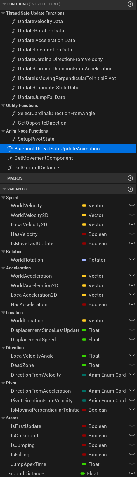
Section titled “4.3.1 Thread-Safe Data Driver — Thread Safe Update Animation”Traditional animation Blueprints execute a large amount of Tick logic every frame in the Event Graph, which can easily become a game-thread bottleneck. In the Lyra architecture, the BlueprintThreadSafeUpdateAnimation function, located in the main animation Blueprint, takes over data updates. With UE5’s Property Access system, it directly accesses the CharacterMovementComponent from the worker thread, extracts rotation, velocity, acceleration, and character state data, and caches them as native Float or Bool values. The role of each function is explained below.
The benefit is that expensive animation-solving logic is moved away from the game thread, reducing CPU overhead and helping maintain stable frame rate under extreme conditions.

A. Base Physical Data Updates
Section titled “A. Base Physical Data Updates”-
Update Velocity: reads the character’s world-space velocity vector from the CharacterMovementComponent, using Property Access nodes, and calculates Ground Speed. This is the core data driving the animation state machine. It determines the character state, such as Idle or Moving, and Ground Speed directly drives the play rate for Distance Matching so that footsteps match movement speed.
-
Update Acceleration: reads the current input acceleration, which represents player movement intent. During startup, before velocity has built up, the animation system must rely on acceleration to predict where the player wants to move and immediately play the correct start animation.
-
Update Rotation: reads the Actor Rotation in world space, which is used to calculate the difference between the character facing direction and the player camera direction.

B. Direction and Displacement Solving
Section titled “B. Direction and Displacement Solving”-
Update Locomotion: calculates and caches the actual displacement between frames (
DisplacementSinceLastUpdate) and the displacement-based speed (DisplacementSpeed). These are the core input sources for Distance Matching. The system drives animation playback progress based on actual travel distance rather than time alone, reducing foot sliding at the physical layer. -
Update Cardinal Direction from Velocity: quantizes the continuous 360-degree movement direction into four enum values: F, B, L, and R. It is mainly used to select the stop animation. When the player releases directional input instantly, the system uses the current velocity direction to decide which stop animation should play.
-
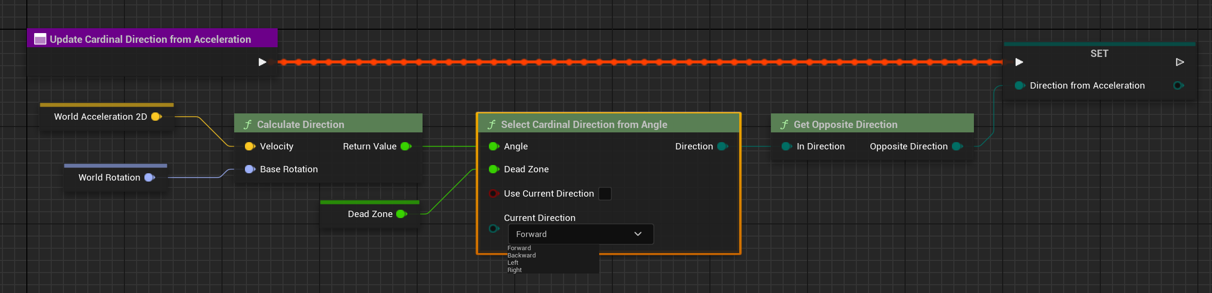
Update Cardinal Direction from Acceleration: quantizes player input intent into four discrete directions. It is mainly used for Start and Pivot animation selection. For example, if velocity is forward but acceleration suddenly points backward, the system recognizes this as a reversal and triggers a Pivot animation.
-
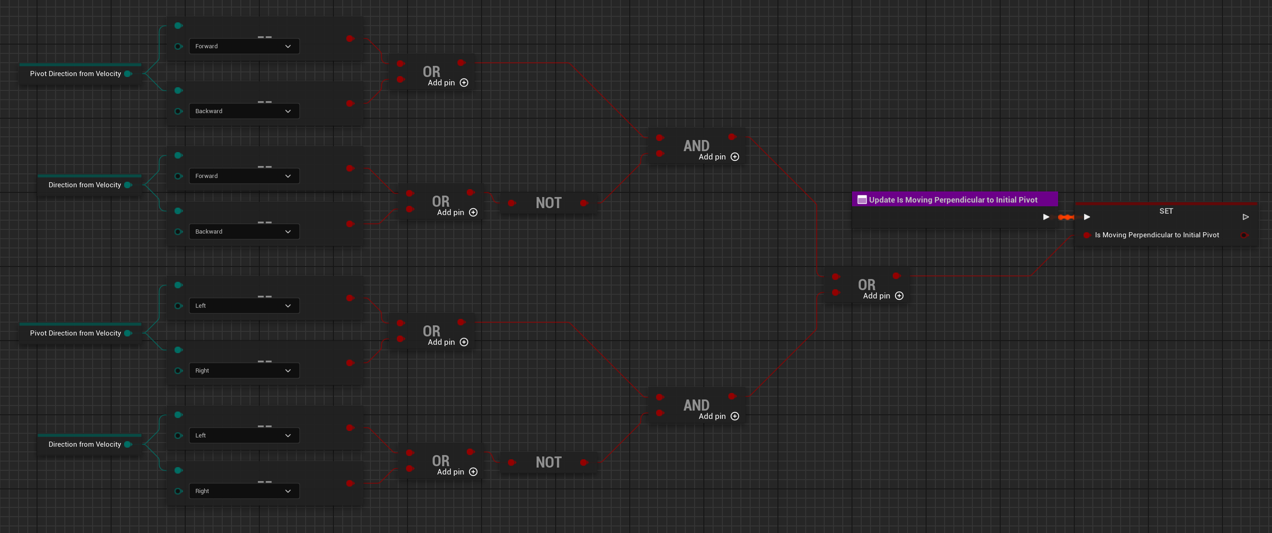
Update Is Moving Perpendicular to Initial Pivot: detects whether the player is making a right-angle turn or a complex mixed input, such as switching from holding W to suddenly holding D. It improves Pivot feel and keeps motion transitions smooth under complex movement input.
C. State and Environment Awareness
Section titled “C. State and Environment Awareness”-
Update Character State Data: reads the current movement mode from the movement component and converts it into Bool states used by the animation system. This is the basis for Locomotion / Jump state transitions in the main state machine.
-
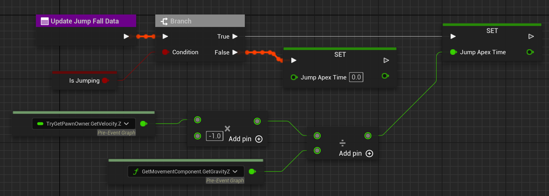
Update Jump Fall Data: calculates and sets
JumpApexTime, the timestamp of the jump apex. This is the moment when the vertical velocity on the Z axis changes from positive to negative and the character begins falling. By calculatingCurrentTime - JumpApexTime, the system obtainsTimeFromApex, the duration since falling began. This drives Fall Loop blending and supports landing prediction logic.
4.3.2 Layered Animation Interface — Linked Anim Layers
Section titled “4.3.2 Layered Animation Interface — Linked Anim Layers”To solve the high coupling of traditional animation Blueprints, Lyra introduces Linked Anim Layers. This separates the logic container from concrete presentation assets and provides two major benefits: module decoupling and high extensibility.
ABP_CyberSkaterBase is essentially a layered state machine. It does not directly contain animation sequences. Instead, it calls child layers through Linked Anim Layer nodes.
2.1 Animation Layer Interface Definition — Anim Layer Interface
Section titled “2.1 Animation Layer Interface Definition — Anim Layer Interface”To decouple logic and presentation, the first step is defining an Anim Layer Interface. In this project, the ALI is not a simple upper/lower body split. It uses a more action-game-oriented state-based fine-grained layering pattern.
-
Template convention:
ALI_AnimLayerInterfacedefines the standard slots of the animation system. These slots are essentially templates and contracts. They do not contain concrete animation assets. Instead, they define which State Slots exist in each child Blueprint, and the main Blueprint dynamically calls these slots through state logic declarations. -
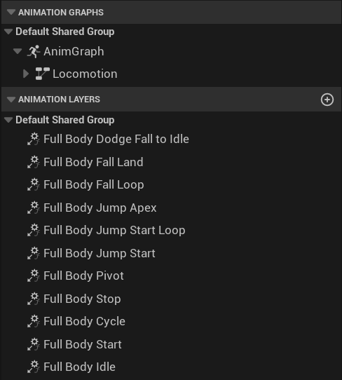
Concrete slot definitions: the interface covers the full movement cycle and ensures precise control over motion blending. It includes:
- Ground locomotion: Idle, Start, Cycle, Stop, Pivot
- Airborne locomotion: Jump Start, Jump Start Loop, Jump Apex, Fall Loop, Fall Land, DodgeFallToIdle, which represents landing recovery after an aerial dodge
-
Dynamic invocation mechanism: the main animation Blueprint,
ABP_CyberSkaterBase, maintains the transition logic of the core state machine, determining which state to enter under which conditions. The concrete animation data is delegated through the interface to child Blueprints, or Linked Anim Layers, where the corresponding animation is played. This decouples logic decisions from animation assets.
2.2 Main Blueprint Logic Pipeline — ABP_CyberSkaterBase (AnimGraph)
Section titled “2.2 Main Blueprint Logic Pipeline — ABP_CyberSkaterBase (AnimGraph)”In the AnimGraph of ABP_CyberSkaterBase, I built a standardized pose-processing pipeline:
Locomotion State Machine, described below, → Inertialization, a key Lyra node that smooths transitions between all states and allows the state machine to perform rapid pose changes while preserving visual continuity → Slot DefaultSlot for montages → Control Rig for procedural IK, enabled when IsFalling = False to prevent leg stretching in the air.

2.3 Core Implementation: Locomotion State Machine
Section titled “2.3 Core Implementation: Locomotion State Machine”The Locomotion State Machine handles the concrete transition logic between states. It uses Conduits and State Aliases to build a highly responsive logic network. The full state machine can be divided into three modules: grounded movement, airborne movement, and landing decisions.
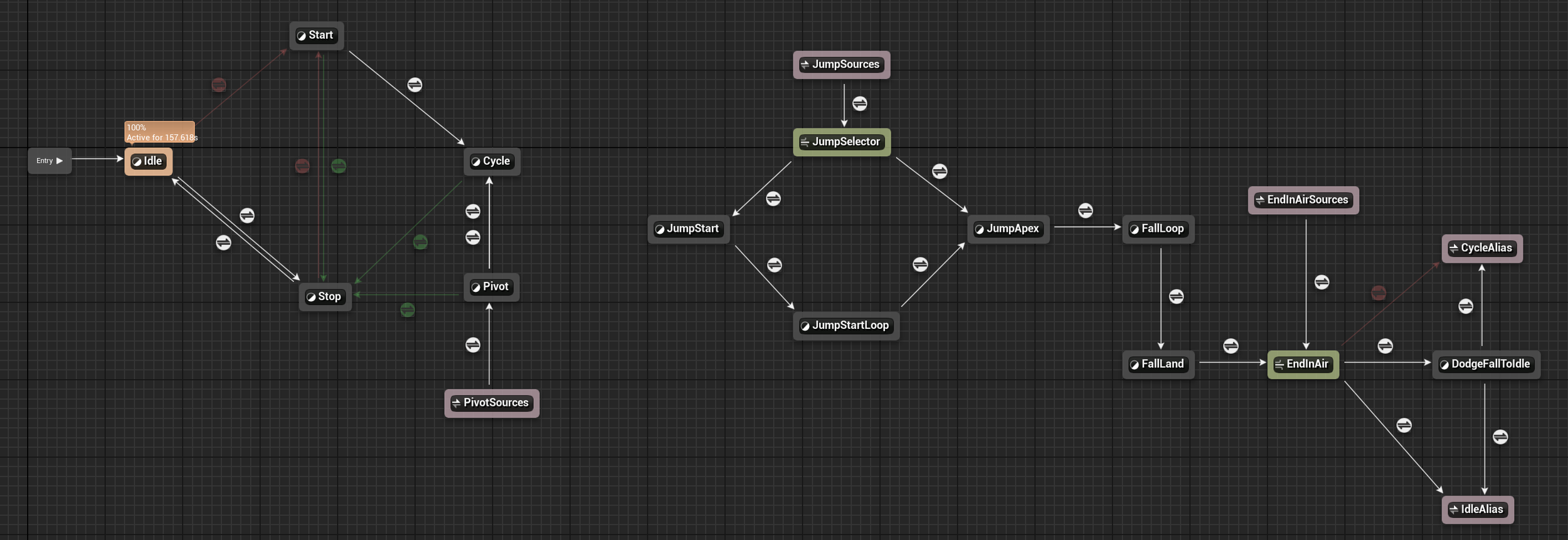
Grounded Loop
Section titled “Grounded Loop”The character’s most basic movement loop is fully driven by Distance Matching.
| State | Entry Condition | Exit Condition |
|---|---|---|
| Idle | State machine origin; returns here after landing with no input | Velocity + acceleration → Start |
| Start | Velocity and acceleration detected | Playback complete → Cycle; no acceleration → Stop |
| Cycle | Start playback complete | No acceleration → Stop |
| Stop | No acceleration; Distance Matching predicts the stop location and determines left/right foot placement | Playback complete → Idle; new input → Start |
| Pivot | Dot product of velocity and acceleration < 0, meaning direction reversal | No acceleration → Stop; lateral input → Cycle |
Airborne Loop
Section titled “Airborne Loop”To achieve a nuanced jump feel, the motion from takeoff to landing is divided into five States:
| State | Description |
|---|---|
| JumpSources | State Alias that centralizes every source that can enter jump: Idle / Start / Cycle / Stop / Pivot / DodgeFallToIdle |
| JumpSelector | Conduit node: IsJumping=True (Vz > 0) → JumpStart; IsFalling=True (Vz < 0) → JumpApex |
| JumpStart → JumpStartLoop | Ground push-off → ascending loop |
| JumpApex | Transitional state representing the weightless moment of gravity reversal. Remaining time is computed with -Vz/g; the state enters when the value is < 0.4s, reserving lead time for animation blending. |
| FallLoop | Falling loop animation |
| FallLand | Landing absorption. Enters when GroundDistance < 200; exits when playback finishes and IsOnGround=True. |
Landing Decision
Section titled “Landing Decision”Branching after airborne motion is handled by EndInAir (Conduit):
| Condition | Target State |
|---|---|
IsOnGround=True and velocity + acceleration exist | → CycleAlias, returning to grounded Cycle |
IsOnGround=True and no velocity or acceleration | → IdleAlias, returning to grounded Idle |
| Velocity exists but there is no acceleration, such as residual momentum after dodge | → DodgeFallToIdle |
4.3.3 Extension and Procedural Correction: Logic Driver Layer — ABP_ItemLayerBase
Section titled “4.3.3 Extension and Procedural Correction: Logic Driver Layer — ABP_ItemLayerBase”ABP_ItemLayerBase is the core logic base class in the animation system. It uses object-oriented inheritance to encapsulate all low-level algorithms related to procedural correction.
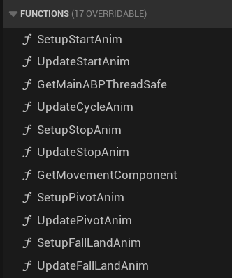
This class contains a series of Setup and Update functions that are directly bound to SequenceEvaluator nodes inside the state machine, allowing precise physical control over animation playback progress.
-
Setup functions: bound to Entry nodes in the state machine. They select the correct animation asset, or Sequence, based on the current character state, such as velocity direction, and reset the SequenceEvaluator’s Explicit Time to the initial value, usually 0.0, preparing for later calculations.
-
Update functions: bound to Update nodes in the state machine and responsible for real-time driving. Every frame, they calculate the character’s actual physical displacement or predicted target point, use mathematical algorithms to determine which frame of the animation should be played, namely Explicit Time, and force animation progress to synchronize with world-space physical movement.
Through Setup zero-time reset and Update real-time prediction, ABP_ItemLayerBase creates a closed loop: physics determines displacement, displacement drives animation. Regardless of changes in ground friction, this logic keeps the character’s feet from sliding and achieves high-precision locomotion presentation.
Case Study: Stop Logic and Distance Matching
Section titled “Case Study: Stop Logic and Distance Matching”The Stop state, specifically the UpdateStopAnim function, is the most typical use case for Distance Matching. To solve the foot-sliding problem where the character’s physical sliding distance after releasing input does not match the stopping distance in the animation, I implemented physics-prediction-based distance matching here.
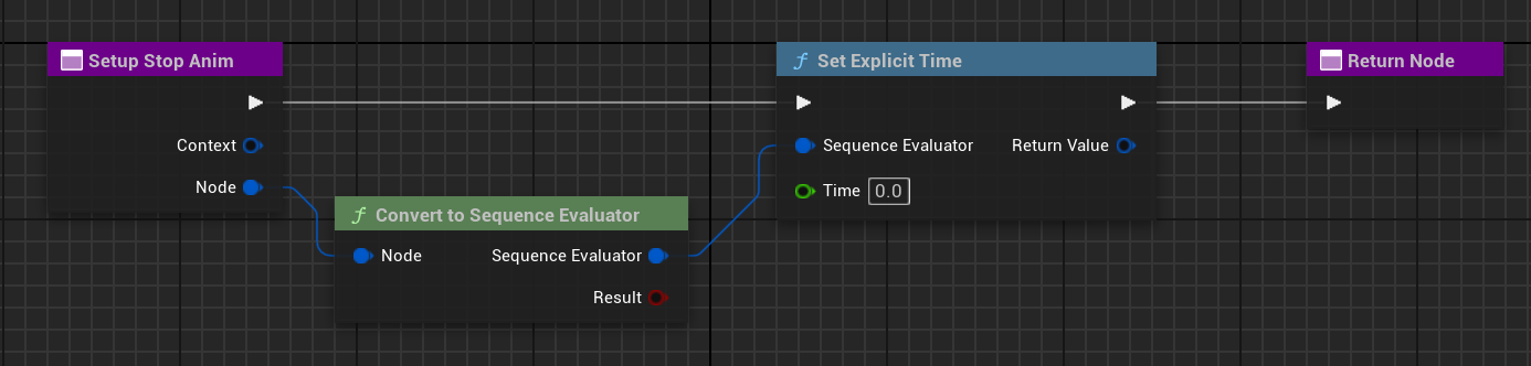
State initialization through Setup StopAnim: when the state machine detects that velocity has dropped to 0 or input has stopped, it automatically calls the Setup StopAnim function. This function performs two key steps. First, it forcibly converts the current animation node to a SequenceEvaluator, cancelling automatic playback and letting code take over animation progress. Then it resets time with Set Explicit Time, forcing animation progress back to 0.0 seconds. This ensures every Stop action starts from the first animation frame, providing a deterministic T = 0, Distance = 0 reference point for later distance calculation.
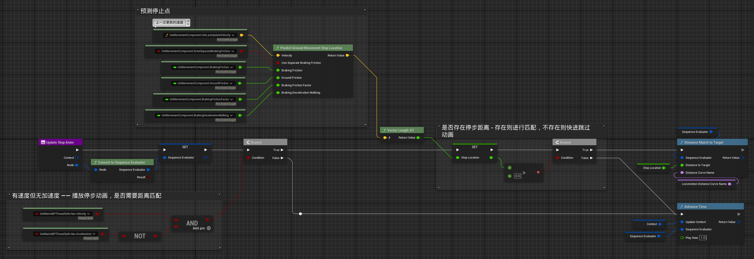
Real-time frame driving through Update: after initialization, the system calls Update StopAnim every frame and uses Distance Matching to correct animation progress in real time. The logic flow is:
-
Physical prediction (Predict Ground Movement Stop Location): the core node is
Predict Ground Movement Stop Location. It reads physical parameters from the CharacterMovementComponent, such as current velocity, Friction, and BrakingDeceleration, then uses physics formulas to calculate the final position where the character would naturally stop under the current ground friction. -
Distance calculation (Stop Location): calculates the distance between the current character position and the predicted stopping position, producing the remaining distance to the target, called Stop Location, and updates it every frame.
-
Distance Matching: the data is passed into the
Distance Match to Targetnode. This node queries the distance curve of root motion displacement in the stop animation and matches the input distance to the corresponding animation frame on that curve, determining which frame the animation should play from.AnimExplicitTime = DistanceCurve.Evaluate(PredictedStopDistance)Example: if physical calculation shows that the character still needs to slide 1.5 meters before stopping, the node forces the animation to jump to the frame that is 1.5 meters away from the animation’s final stopping pose.
-
Boundary handling (Branch): two Branch nodes provide safeguards. If distance matching is unnecessary or physical prediction fails, such as when the stopping distance does not exist or is extremely short, the system falls back to
Advance Time, the normal time-advance node. This prevents the animation from freezing and ensures continuous visual feedback.
Modular Layer Encapsulation + Orientation Warping / Stride Warping
Section titled “Modular Layer Encapsulation + Orientation Warping / Stride Warping”If the Setup and Update functions above define which logic algorithm executes after entering each State, and the Stop case explains how those algorithms work, this section explains how the “execution container” for that logic is constructed.
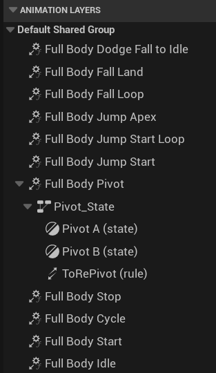
I instantiate every standard slot in the 4.3.2 interface (ALI), such as Full Body Start and Full Body Pivot, as an independent Animation Layer. This “state as layer” design pattern creates atomic logic encapsulation: every action state becomes an independent unit with a complete execution flow.
Using the Pivot A layer as an example, a standard layer implementation contains a Sequence Evaluator and final Output node. Procedural deformation steps can then be added on top of this. The role of each node is:
-
Sequence Evaluator node binding: this is the bridge between the Setup/Update functions and the layer. Through the Sequence Evaluator node, when the state machine enters this layer, namely On Become Relevant, the animation node inside the graph automatically calls
SetupPivotAnimin the base class. While the layer continues updating, namely On Update, it continuously callsUpdatePivotAnim. -
Space conversion: Local To Component / Component To Local: later Warping nodes need to perform bone calculations in Component Space, so the flow converts from Local To Component and then back from Component To Local.
-
Orientation Warping: by reading Locomotion Angle, the lower body continues following the Pivot animation while the spine bones are forcibly twisted so that the upper body always faces the player’s actual input direction.
-
Stride Warping: by reading Locomotion Speed, the stride length of both legs is dynamically stretched or compressed during the pivot to match the capsule’s actual movement speed, further reducing foot sliding.

It is worth noting that a layer does not have to contain only one animation node. It can also contain a more granular sub-state machine. For example, Pivot_State contains a small state machine for choosing Pivot A (left reversal) or Pivot B (right reversal). This demonstrates the strength of Lyra’s layered architecture: the macro state machine controls flow, while the micro layer handles detail.
4.3.4 Asset Configuration and Concrete Implementation — ABP_LocomotionLayers
Section titled “4.3.4 Asset Configuration and Concrete Implementation — ABP_LocomotionLayers”If ABP_ItemLayerBase in section 4.3.3 defines the structure and logic, ABP_LocomotionLayers defines the actual animations that each structure should execute. As a concrete child class of ABP_ItemLayerBase, this Blueprint shows the final form of logic/resource decoupling in the Lyra architecture: zero logic, pure data.
The only responsibility of this Blueprint is to inject concrete animation sequences into the slots reserved by the parent class through Asset Override variables. Once these variables are assigned, the parent class’s Setup/Update functions automatically read the concrete animation assets at runtime and apply them to the corresponding Sequence Evaluators.
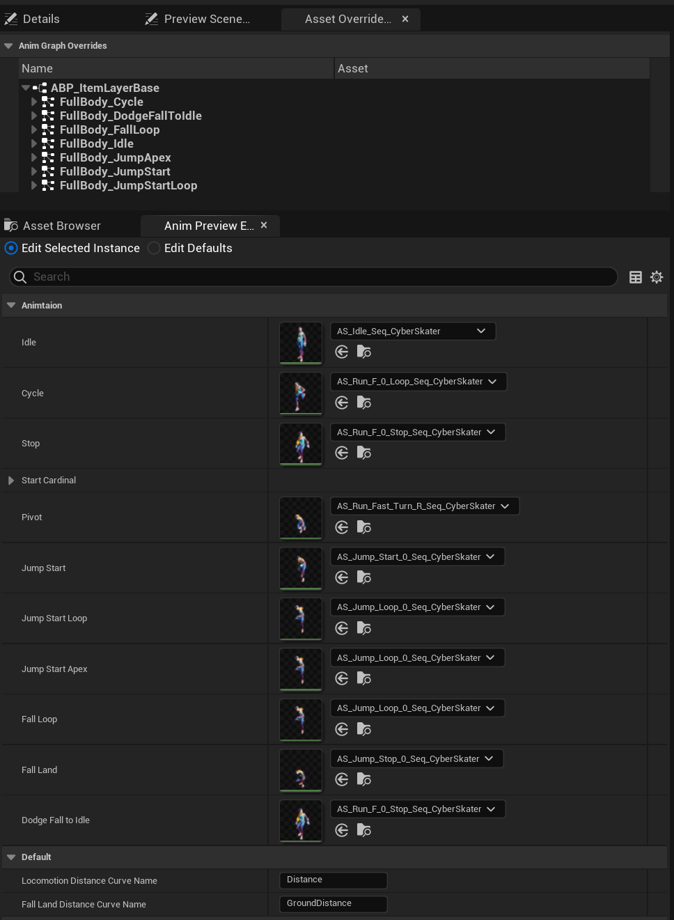
The advantage is a complete decoupling between the logic layer and presentation layer. When animation or design content is configured, changes to the presentation layer cannot break the underlying state-machine logic or algorithms. This architecture is also highly reusable and extensible. If I want to create another multiplayer character, a weapon variant for the current character, or an injured-state version of the protagonist, I only need to create a new child Blueprint inheriting from ABP_ItemLayerBase and replace the animation assets inside it. One set of logic can drive many entirely different styles of motion presentation.
4.4 Procedural Physical Correction — Control Rig Foot IK
Section titled “4.4 Procedural Physical Correction — Control Rig Foot IK”At the end of the animation pipeline, I introduce Control Rig to handle Foot IK. This is the key to believable interaction between the character and environment such as slopes, stairs, and obstacles.
4.4.1 Technical Selection: Why Use Control Rig Instead of Traditional IK?
Section titled “4.4.1 Technical Selection: Why Use Control Rig Instead of Traditional IK?”In the UE4 era, Two Bone IK nodes in AnimGraph were commonly combined with complex Blueprint trace logic. In this project, I moved fully to Control Rig, mainly for the following advantages:
-
Logic visualization and encapsulation: in the traditional approach, trace logic is written in CharacterBP while animation correction is written in AnimBP, scattering logic and making it difficult to debug. In Control Rig, all trace detection, math calculation, and bone transform logic is encapsulated inside
CR_CyberSkater_Mage_BasicFootIK. The logic and Debug Flow are directly visible, making the implementation much easier to inspect. -
More natural full-body solving (Full Body IK integration): traditional Two Bone IK simply folds the knee, which can easily create stiff or unnatural bending. Control Rig uses the Full Body IK (FBIK) solver. When the foot is raised, it not only bends the knee but also naturally adjusts pelvis height and even spine posture, producing a coordinated full-body pose.
-
Zero-cost blending when disabled: as shown in the AnimGraph, the
ShouldDoIKTracevariable controls the entire Rig. When the character is airborne, IK logic stops completely, reducing performance cost.

4.4.2 Core Implementation Logic
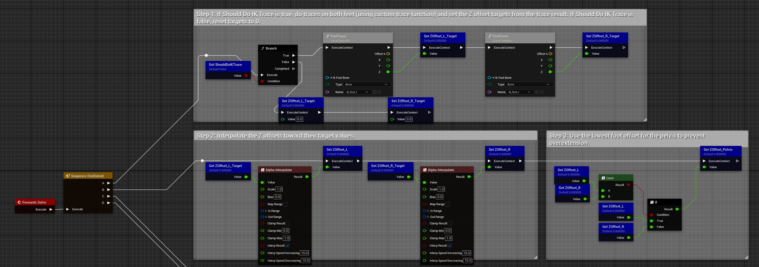
Section titled “4.4.2 Core Implementation Logic”Inside Control Rig, the logic strictly follows the standard pipeline of detection → smoothing → offset → solving, divided into five steps:
-
Step 1 - Environment sensing: first checks whether
ShouldDoIKTraceis enabled. If enabled, sphere traces are cast downward from both foot positions. The ground height below each foot is obtained, and the height difference between the sole and the actual ground is calculated asZOffsetTarget. In other words, it measures how much the foot is floating or penetrating the ground. -
Step 2 - Signal smoothing: trace data changes instantaneously. For example, when stepping onto a stair, directly applying the value would make the foot snap to the stair. This step uses interpolation nodes (
AlphaInterpolate) to smooth the value and avoid jitter. -
Step 3 - Pelvis adaptation: compares the offsets of both feet and takes the lower value to adjust the pelvis height (
ZOffset_Pelvis). -
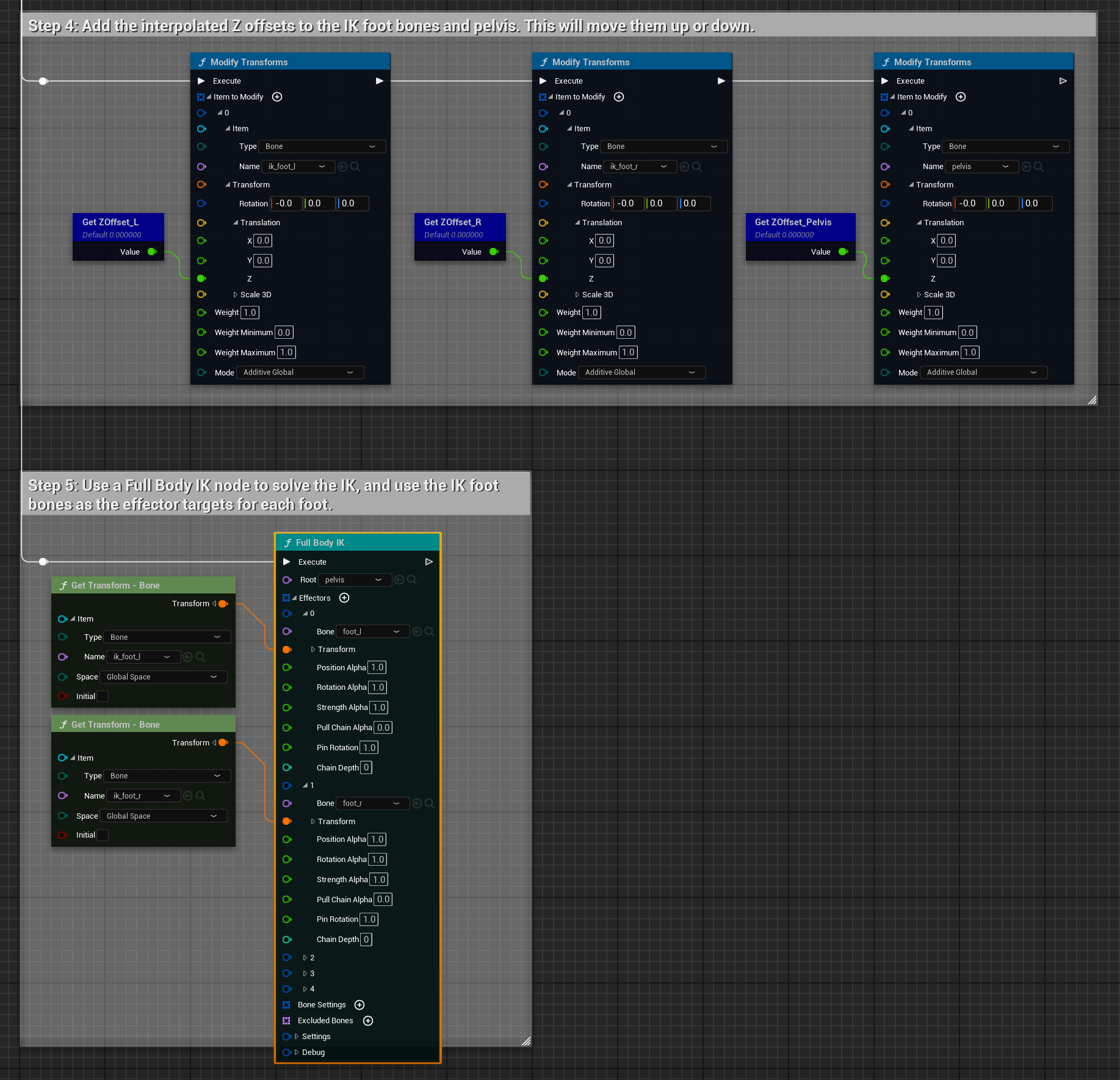
Step 4 - Apply offsets: the calculated Z Offset is passed into Modify Transform nodes and applied to the virtual IK bones (
ik_foot_l,ik_foot_r) and the pelvis. At this stage, the IK target points are aligned to the ground, but the actual leg bones have not moved yet. -
Step 5 - Full-body solve: finally, the Full Body IK node is called. The
ik_footbones moved in Step 4 act as Effectors. The FBIK solver automatically computes the rotation angles of the thigh, calf, and ankle so the bone chain naturally reaches those target points.